


Ultrasonic Drill (Project in Progress)
- Oct 24, 2017
- 3 min read

Sep. 25, 2017
I am currently working on my capstone project as part of an interdisciplinary project building an ultrasonic drill. The team consists of myself and one other mechanical engineering major with four electrical engineering majors. From the mechanical side, we are responsible for a functioning sonotrode and bit assembly with which to magnify the amplitude of the ultrasonic vibrations provided by a piezoelectric transducer. In addition, we must provide a functioning motorized lift platform on which to clamp the working material, this will require the programming and use of an Arduino Uno microcontroller and a stepper motor driven linear actuator (the other mechanical engineering major and myself both requested this project due to our interest in mechatronics). We are also responsible for a structural frame, basin, and method of delivering slurry, the grinding agent used to transmit energy from the bit and chip away at the working material.
So far, the project has been an interesting challenge. A great deal of research has been required to determine how to best describe and model the ultrasonic interactions occurring. It has certainly improved my ability to selectively find information and teach myself new subjects.


Oct. 20, 2017
As an update, I have manufactured a prototype sonotrode assembly, apart from soldering the bit into the brass screw which will be used to attach it to the sonotrode. From my research, the process of silver-soldering takes a bit of practice, and with how pivotal the connection of the drill bit is, I have decided to wait and find help from someone experienced with silver-solder.
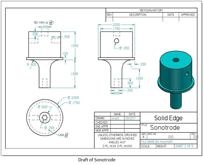
The sonotrode itself was turned down on a lathe. As this was my first lathe project, and with the mechanical sensitivity of the sonotrode, I decided it would be best to make a prototype before manufacturing the final part. To function properly, the sonotrode must have a longitudinal resonance near the operating frequency of the transducer. This requires tuning when manufacturing. For the final sonotrode, we will have to form the step shape but leave the length long on either end and systematically machine down the ends until the resonance is ideal. To measure the resonance, we must re-drill, tap, and mount both the transducer and bit mount, attach the transducer to an electric wave generator and measure the frequency at which power is optimized, in between every cut on the lathe. Needless to say, it will be an involved process. Aluminum was chosen for the sonotrode due to its low cost, high machinability, and low acoustic impedance. Specifically, 6061-T6511 was chosen, primarily due to availability.
Currently, the prototype sonotrode bolts to the transducer. A mounting point on the sonotrode is sandwiched between two 3D printed mounting brackets, separated on either side by silicone o-rings. These mounting brackets are then bolt to an aluminum plate containing a hole through which the sonotrode protrudes. This plate can be clamped to desktops and such for testing of the prototype. Images of the sonotrode assembly as both the CAD model and manufactured prototype can be seen below.
Beyond the sonotrode, my teammate and I have successfully connected and programmed the Arduino to control the vertical axis linear actuator we plan to use for the motorized lift platform. Also, we have made a prototype slurry delivery system. The key issue is that the abrasive quality of the slurry would deteriorate most pumps quite quickly, and the pumps designed to withstand these conditions seem to be well beyond the budget of our entire project. So, we have opted for a gravity fed system. However, when using heavy concentrations of slurry, stagnation in the holding tank would cause issues. We are attempting to overcome this issue by using an air pump to mix the slurry suspension while it rests in the tank. Videos for these parts of the project can be seen below.


Lift Mechanism Prototype Video
Slurry Delivery Prototype Video
Comments